August 9, 2026
What is flight test instrumentation and why is it important?
Flight test instrumentation (FTI) is the specialised monitoring equipment fitted to an aircraft during flight testing.
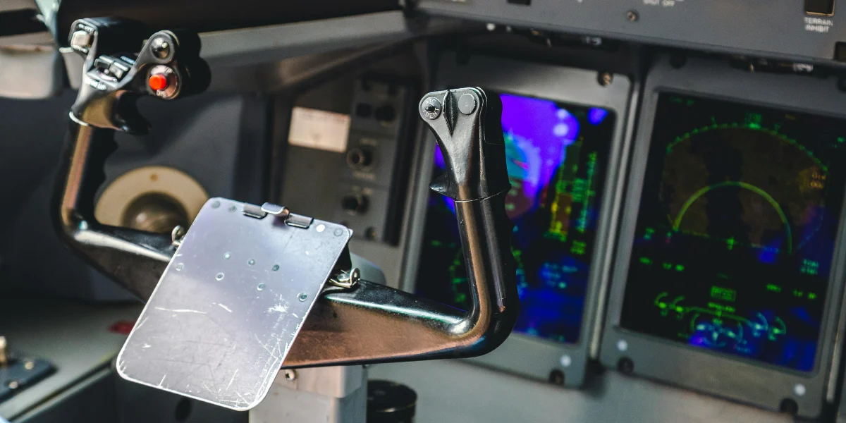
Flight test instrumentation (FTI) is the specialised monitoring equipment fitted to an aircraft during flight testing. It measures how the aircraft performs by gathering data on parameters such as speed, altitude, temperatures, control inputs and system behaviour.
These insights are an essential part of aircraft certification, providing the evidence needed to demonstrate an aircraft performs as intended. They are also a crucial input to the development of high-fidelity full flight simulators (FFSs), helping manufacturers accurately replicate how an aircraft behaves under a wide range of operating conditions.
What are the key components of a FTI system?
A FTI system is made up of a network of sensors and data acquisition equipment. Each component measures a different aspect of performance, providing engineers with the information they need to evaluate handling qualities, structural integrity and overall system characteristics.
The breadth of FTI often surprises people. Rather than relying on a handful of sensors, modern FTI systems capture hundreds – and often thousands – of individual parameters during a single test flight. Without this wealth of data, engineers simply wouldn’t have the insight needed to validate aircraft performance or understand how the aircraft behaves in real-world conditions.
Some of the key components include:
- Accelerometers (piezoresistive or piezoelectric): Accelerometers measure vibration and motion throughout the aircraft. During flight testing, they’re used to record acceleration along different axes and monitor the aircraft’s pitch, roll and yaw rates. This data helps engineers understand how the aircraft responds to pilot inputs, turbulence and manoeuvres, while also identifying unwanted vibration that could affect performance or passenger comfort.
- Strain gauges: Strain gauges are attached to structural components such as wings, the fuselage or landing gear to measure how much they bend or flex under load. By recording structural strain during different flight conditions, engineers can confirm that the aircraft is performing within its design limits and validate structural models used during development.
- RVDT and LVDT position sensors: Rotary Variable Differential Transformers (RVDTs) and Linear Variable Differential Transformers (LVDTs) measure the movement and position of components throughout the aircraft. They’re commonly used to monitor control surfaces such as ailerons, elevators and rudders, as well as cockpit controls, steering systems and landing gear struts. These sensors allow engineers to compare pilot commands with the aircraft’s physical response.
- Load cells: Load cells measure the forces applied to aircraft controls, including the amount of force a pilot exerts on the control column or yoke. This information is particularly valuable when assessing handling qualities, ensuring the aircraft provides the expected level of control feedback and pilot workload.
- Thermocouples: Thermocouples measure temperature at key locations throughout the aircraft, including engines, hydraulic systems and other critical components. Monitoring temperature helps engineers verify that systems remain within their operating limits and perform reliably throughout the flight envelope.
- Pressure sensors: Hydraulic pressure sensors monitor the health and performance of hydraulic systems responsible for operating flight controls, landing gear and brakes. Air pressure sensors also play an important role, particularly when measuring pitot and static pressures or monitoring environmental systems.
- Air data sensors and nose boom instrumentation: Many flight test aircraft are fitted with a nose boom carrying specialised sensors, including angle-of-attack (alpha) and sideslip (beta) vanes. Positioned ahead of the aircraft to avoid airflow disturbances, these instruments provide highly accurate air data that’s essential for evaluating aerodynamic performance, stability and control characteristics.
- Avionics data bus interfaces (ARINC 429 and other digital buses): On modern digital aircraft, much of the information engineers need is already available through the aircraft’s avionics systems. Rather than installing additional sensors, FTI can capture data directly from digital buses such as ARINC 429. This provides access to hundreds of aircraft parameters, including engine information such as Inter-Turbine Temperature (ITT), N2 speed, fuel flow, flight management system data, navigation information and numerous aircraft system parameters. Accessing existing digital data reduces the need for extra hardware while providing a rich source of high-quality flight information.
Data acquisition and recording systems
Collecting measurements is only part of the job. The analogue signals generated by many sensors are first conditioned to remove noise and ensure they’re suitable for recording before being sent to the data acquisition unit. Here, they’re converted into digital data, precisely time-stamped and synchronised so engineers can accurately correlate information from hundreds of different sources throughout the flight. This process creates a single, coherent dataset that can be analysed after the flight or transmitted to engineers on the ground in real time.
Many test aircraft are also equipped with cameras inside the cockpit to provide an overview of the flight deck, allowing engineers to observe pilot workflow and interactions with aircraft systems. Additional close-up cameras are often used to record the Primary Flight Display (PFD), Multi-Function Display (MFD) and other cockpit instruments, preserving exactly what the crew saw during each phase of the test.
Microphones may also be installed to capture ambient cockpit sounds, while connections to the aircraft’s intercom system can record crew communications, warning tones, chimes and aural alerts. These recordings provide valuable context that help engineers interpret the sensor data and investigate any anomalies identified during the flight.
Tailored instrumentation set up
Every flight test is designed to answer a specific question and that objective shapes the instrumentation required. Whether the goal is to demonstrate compliance for certification, investigate stall characteristics, clear the aircraft for flutter, measure structural loads or validate a new system, the first step is defining exactly what evidence the flight needs to provide. This forms the test matrix – a detailed plan setting out every manoeuvre to be flown and the parameters that must be recorded.
With the matrix established, attention turns to how those measurements will be captured. Each sensor is selected and positioned according to the data required, balancing measurement accuracy against practical considerations such as weight, available space, installation access and aerodynamic interference. For example, strain gauges and accelerometers are placed along the structural load paths or areas of vibration being investigated to ensure they capture meaningful data.
The FTI architecture is designed simultaneously. This includes determining how data will be acquired across the aircraft, whether through a centralised or distributed acquisition system, how wiring will be routed, how the equipment will be powered and how the additional hardware will affect the aircraft’s weight and centre of gravity. On modern digital aircraft, many parameters are also captured directly from avionics data buses, such as ARINC 429, providing access to engine, navigation and aircraft systems data through strictly read-only interfaces that ensure the instrumentation can never influence the aircraft’s operation.
The installation itself is engineered as a formal aircraft modification. Every mount, bracket and cable must be shown to withstand the same flight loads as the aircraft, while electromagnetic compatibility (EMC) and electromagnetic interference (EMI) testing demonstrates that the instrumentation will not interfere with onboard systems or compromise airworthiness.
Before the first test flight, the entire system undergoes calibration and verification. Every sensor and data channel is calibrated end-to-end against traceable standards, followed by comprehensive ground functional checks to confirm that measurements are accurate, synchronised and ready for flight. Only once those checks are complete is the aircraft cleared to begin collecting flight test data.
How FTI is evolving
FTI has always evolved alongside aircraft design. As avionics become more sophisticated and software takes on a greater role in controlling how an aircraft behaves, the data engineers need is changing too.
Modern aircraft generate huge volumes of digital information through fly-by-wire systems and integrated avionics. Increasingly, FTI can access information directly from the aircraft’s data buses, giving engineers insight into everything from engine performance to flight control logic. That doesn’t mean physical sensors are becoming obsolete, though.
Independent measurements remain essential. In many cases, engineers install their own sensors to verify that the aircraft is behaving exactly as its onboard systems report. There are also situations where the aircraft already measures a particular parameter, but not at the sampling rate needed for detailed flight test analysis. Dedicated instrumentation fills those gaps, providing the higher-resolution data needed to capture fast-moving events such as structural vibrations or flutter.
The technology behind those measurements is evolving as well. Fibre-optic sensing, for example, allows hundreds of strain or temperature measurements to be carried over a single fibre, dramatically reducing wiring weight while increasing the amount of data available. Wireless sensors are beginning to remove some of the practical challenges of instrumenting complex aircraft, while onboard data processing is becoming capable of identifying anomalies during the flight itself.
The shift beyond the aircraft
High-fidelity flight simulators and digital twins are becoming an important part of aircraft development, pilot training and ongoing fleet support. Their value depends entirely on how accurately they represent the real aircraft, and this can only be achieved using flight-validated data. As demand grows for more realistic simulation, the expectations placed on flight test data continue to rise. Data must be accurate, traceable and collected with the level of fidelity needed to validate more sophisticated models.
New aircraft concepts are adding another layer of complexity. Electric and hybrid-electric propulsion systems introduce entirely new parameters, from individual battery cell behaviour to motor and inverter performance. Autonomous and remotely piloted aircraft bring software decision-making into the picture, requiring engineers to understand not only how the aircraft responds, but why it made a particular decision in the first place. The result is larger datasets, new sensing requirements and an even greater reliance on robust instrumentation.
What happens when the data isn’t there
Because FTI works quietly in the background, it’s easy to underestimate its importance. Shortcomings often don’t become apparent until it’s too late to fix them without significant cost.
One of the most immediate consequences is the need to repeat test flights. If a manoeuvre has been completed but a key parameter wasn’t recorded, the sampling rate was too low or data from different systems can’t be accurately synchronised, the result may be unusable. That means flying the test again – an expensive prospect.
Beyond costs, certification authorities expect accurate flight test evidence to be traceable and fully defensible. If a sensor hasn’t been properly calibrated or timestamps between data acquisition systems don’t align closely enough, confidence in the results can quickly disappear. In some cases, even a small timing error is enough to invalidate complex analyses, particularly when engineers are assessing dynamic behaviour such as flutter.
There’s also a safety dimension that should never be overlooked. Flight testing deliberately explores the limits of an aircraft’s operating envelope, whether that’s stall behaviour, high structural loads, system failures or other demanding conditions. Throughout those flights, engineers rely on live telemetry to monitor structural loads, temperatures, system health and countless other safety-critical parameters. Without reliable instrumentation, the team loses visibility of what’s happening as the aircraft approaches those limits, reducing the information available to make informed decisions during the flight.
FTI is more than installing sensors
Installing FTI involves far more than mounting sensors around the aircraft. Every installation is treated as an engineering modification and must satisfy the same rigorous standards applied to other changes made to the aircraft.
That begins with demonstrating that brackets, mounts and supporting structures can withstand the loads they’ll experience in flight. Engineers also reassess the aircraft’s weight and balance, particularly when cabin equipment has been removed to make space for instrumentation racks and additional wiring. Electrical systems are analysed to confirm there’s sufficient power available, while bonding, grounding and electromagnetic compatibility testing ensure the instrumentation cannot interfere with onboard functions.
Telemetry systems introduce their own considerations, including spectrum licensing and frequency coordination with the relevant aviation authorities and test ranges. Practical details matter too. For example, instrumentation must never obstruct the flight crew, restrict emergency exits or interfere with safety equipment.
Depending on the nature of the modification, approval may be required under EASA, FAA or other national aviation regulations before the aircraft is cleared to fly. Once the campaign is complete, the instrumentation is removed and the aircraft is returned to its approved configuration.
For all the attention given to new aircraft and next-generation simulators, none of those developments can move forward without reliable flight test data. FTI may never be the most visible part of an aerospace programme, but it provides the evidence that allows engineers to understand how an aircraft really behaves. Every successful certification and confident design decision begins with trusted data.
More articles:
September 4, 2026
Why modern aircraft require simulators before entry into service?

December 1, 2025
Trends in Aircraft Modification Programs (STCs)
June 1, 2026